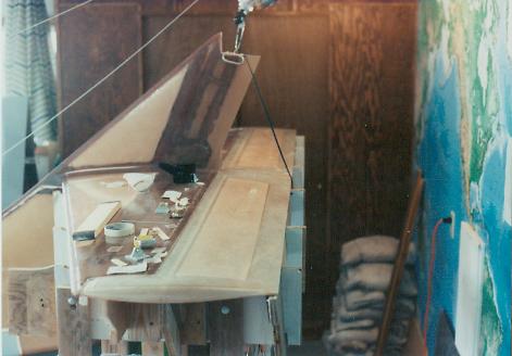
| Fitting and trimming the
elevator skins on the jigs and against the elevator. |
|
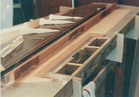
| The elevator shear web has
been fabricated in place. Recesses have been cut into the web for
the attachment hinges.
This view of the right elevator shows
that the trim tab opening has been cut and reinforcing laminates have been
bonded in place. |
|
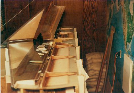
| The elevator ribs have been
installed. |
|
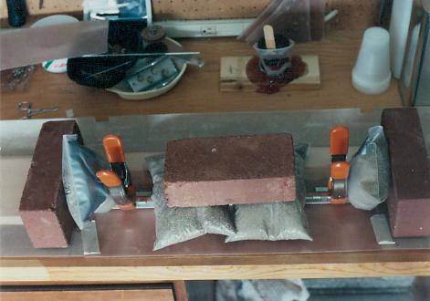
| The trim tab is fabricated
from scratch with foam and fiberglass cloth on the workbench.
This minimizes the final weight of the
trim tab rather than using the pieces cut out from the elevator.
Controlling weight is critical on a
component located so far aft of the center of gravity. In addition,
the trim tab will not be counterbalanced so building it as light as
possible is mandatory. |
|
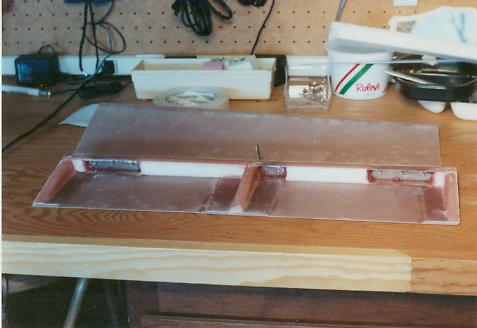
| The trim tab with attachment
hardware is ready for the top skin to bonded in place. |
|
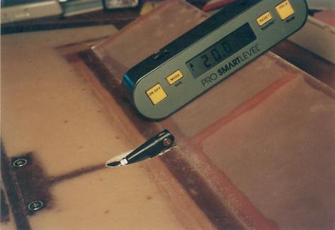
| Here the trim tab is installed
in the elevator and the correct movement and clearances are established.
Full down deflection is 20 degrees from
the neutral position. The assembly is upside down in this picture. |
|
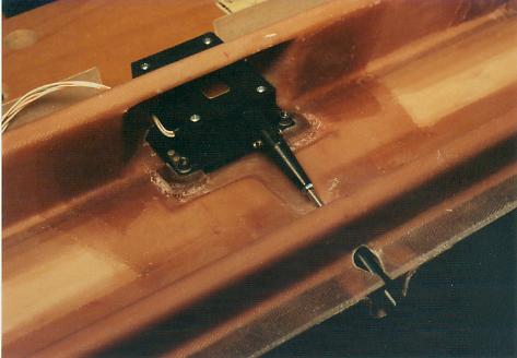
| An electric motor actuates the
trim tab. The motor is installed in the right elevator with a short
push rod being attached to the trim tab. |
|
| The right elevator completed
and ready for the top surface to be bonded in place. |
|
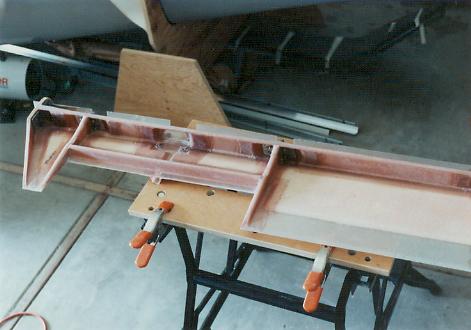
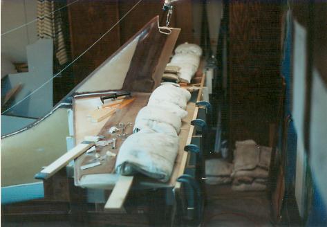
| The top elevator skins are
bonded in place on the support towers.
The elevator is attached to the
horizontal stabilizer and it is hot glued to the towers in the exact
correct position prior to bonding. |
|
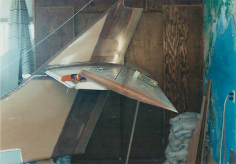
| With the horizontal stabilizer
completed and the elevator completed, the support towers can now be
removed.
A significant moment! |
|
|
|

